FS TUBULAR STEEL MICRIOPILES MULTI-STAGE HIGH PRESSURE INJECTED THRU “MANCHETTES”
Execution of FS Micropiles injected at high pressure, for JG Summit Batangas City Plant.
The main use and application of tubular steel micropiles high pressure injected thru manchettes (rubber sleeves used as check valves) is to underpin the foundations of existing structures, to increase the bearing capacity of the same, for whatever purpose that added bearing capacity may be needed.
Generally, the installation of steel micropiles for underpinning existing structures has to be done in places with limited vertical clearance.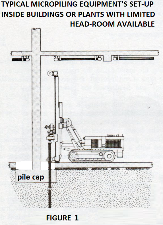 Because of the limited vertical (and horizontal) clearance, the equipment to be used shall be small enough to be able to operate in the available space, likewise, the tubular steel micropile shall be made in segments of a length suitable to be installed within the available vertical clearance. Each segment of the tubular steel micropile reinforcement has to be threaded at both ends (M/F) and provided with grout holes 16mm in diameter and spaced 500mm; each grout hole position covered by rubber manchettes (check valves). Proper spacers will also be provided to keep the reinforcement centred in the hole. The top segment of the tubular steel micropile will be provided with welded rebars as shown in Figure 3. The various segments of the tubular steel micropile reinforcement are provided with manchettes (rubber sleeves acting as check-valves) installed in correspondence of grout holes drilled in the tubular steel every 500mm, which will be used to perform the high pressure multiple stage grouting. Grout injection equipment will consist of piston type injectors , with capacity to inject high volume of grout at high pressure and be able to maintain statically the pressure when needed (Testing). Also needed are grout mixers, grout agitators, and double packers with sectional feeding rods. The sequence of operations to be followed is as follows: the area of the existing reinforced concrete strip footings (which will become pile caps) has to be cleared and the concrete top shall be exposed in preparation for coring or drilling the hole or holes thru which the installation of micropiles will have to be done . The hole thru the pre-existing reinforced concrete strip footing will be done either with coring equipment of DTH. This operation is usually time consuming because of the presence of steel reinforcing bars layers to be taken care of, so this activity has to be carried out by crews different from those in charge of the micropiling execution proper. It is of paramount importance that the boring thru concrete strip footings be started well ahead of micropile installation proper, so that the execution (installation) of micropiles will not be delayed by the unavailability of sufficient number of completed holes thru the concrete strip footing. For the JG Summit Project, the holes to be made thru reinforced concrete shall be no less than 250 mm and no more than 280 mm as stated by the specs. The existing strip footings 1,400 mm thick are made with high strength concrete reinforced at top and bottom with 32mm diameter steel bars reinforcement which, by itself, is an important factor to input in the computation of coring/ drilling time, procurement and stock of coring/ drilling bits. The top of the strip footings shall be all accessible to the drilling rigs, the distance between micropiles is small and to make individual sufficiently large pits in correspondence of micropile positions, will render the area unworkable.
Once the holes thru the reinforced concrete strip footing are done, drilling for the micropiles’ excavation will be done by rotary equipment (see Fig. 1 and Fig. 2 ) of proper dimensions, suited for the available vertical and horizontal clearance of the site.
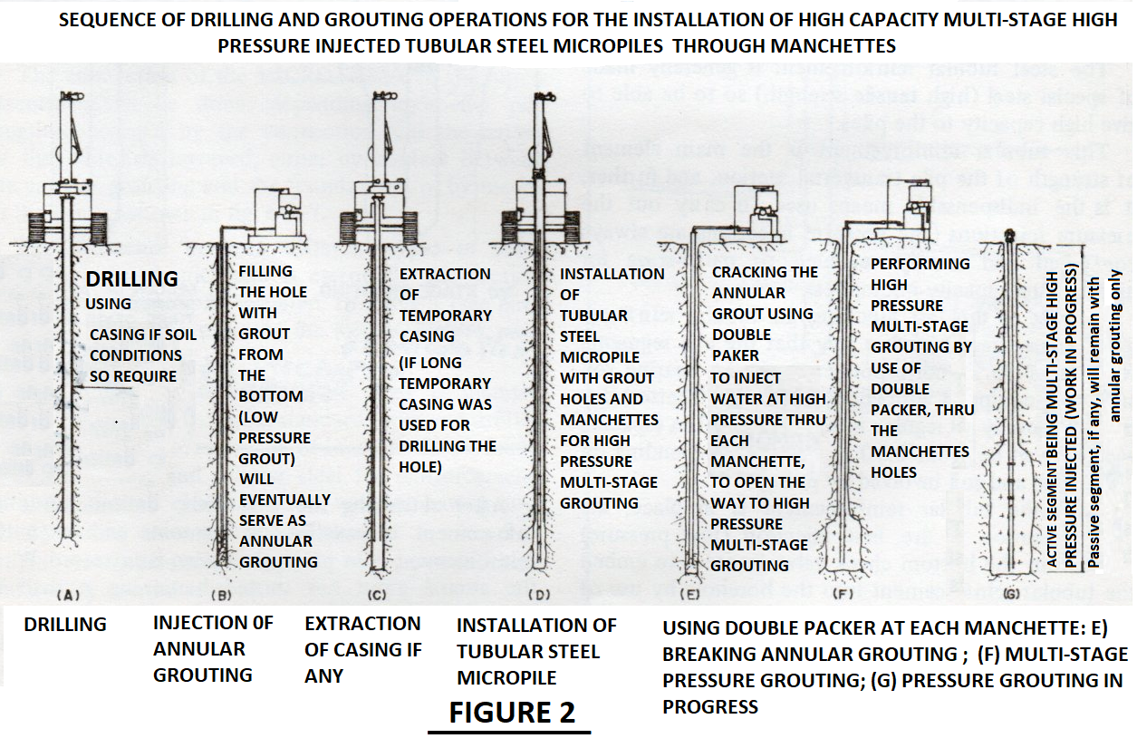
Drillng is done by rotary equipment and the appropriate tool for the soil or rock to be drilled, and the removal of debris produced by drilling will be done using direct circulation of a drilling fluid, which will be preferably water, or suspension of polymers in water or a suspension of bentonite in water. Depending on soil conditions, the temporary steel casing to be used will be either a
short one, or one as long as the hole. 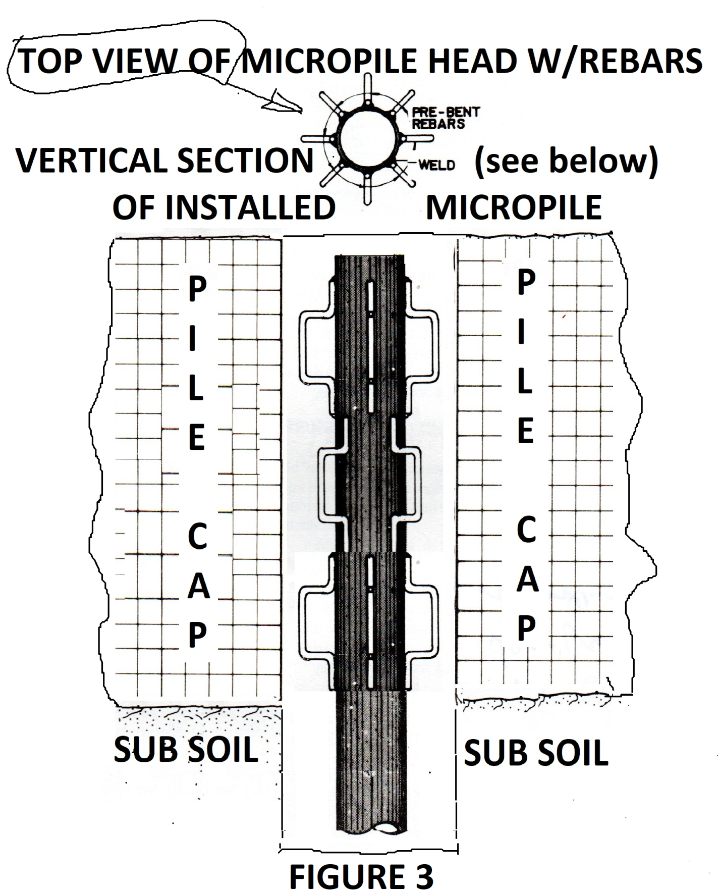
Once the drilling for one micropile hole is completed, a closed bottom tubular steel pipe, which is the reinforcement of the micropile, will be installed by adding and connecting by thread, at the top of the hole, threaded segment to threaded segment, as stated above.
Before being installed in the borehole, the various threaded segments of the steel tubular reinforcement will have been provided with rubber sleeves (Manchettes) acting as check-valves, installed in correspondence of, and covering the grout holes, previously drilled in the tubular steel with a spacing of 500mm for the whole lenth of the tubular steel reinforcement. The grout holes, and the manchettes are used to perform the high pressure, multiple stage, grouting. Once the entire length of the micropile reinforcement is installed (with closed bottom, as already stated above), “annular grouting” is done, filling the hole with cement grout (and displacing the drilling fluid), by performing low pressure grouting to fill the borehole, either using the lowest grout hole of the tubular steel micropile reinforcement and a packer, or thru a hose or pipe with the end positioned at the bottom of the hole. A often used alternative way to perform the annular grouting is to fill the borehole using the drilling pipes, before installing the tubular steel reinforcement, then immediately install into it the steel tubular reinforcement, while extracting the temporary casing (if any was used).
The annular grouting is a necessary means to permit the high pressure of the micropile by preventing the upward movement of the grout. The closed-bottom tubular steel pipe, which is the reinforcement of the micropile, has to be provided with proper spacers, and installed down to the bottom of the drilled hole, as stated above, by adding at the top of the hole, threaded segment to threaded segment, connecting by threads the various segments, until the whole length of the assembled and installed tubular steel reinforcement extends from the hole bottom to the pile head. The top element of the tubular steel reinforcement, with welded rebars (as in Fig. 3) has to be contained within the 1,400 mm reinforced concrete strip, footing. Both the grout to be used for annular grouting and the one for the high pressure grouting are different from what will be needed to anchor the pile head to the strip footing (pile cap), an obturator sack may be installed on the tubular steel micropile, positioned under the strip footing, in which case a vent will be provided bypassing the obturator sack, the vent will perform as the grout return hose or pipe, to assure the complete filling of the hole with annular grouting. Proper spacers will be provided to keep the tubular steel reinforcement centered in the hole. The top segment of the tubular steel micropile will be provided with welded steel bars as shown in Figure 3. The various segments of the tubular steel micropile reinforcement are provided with manchettes (rubber sleeves acting as check-valves) installed in correspondence of grout holes drilled in the tubular steel every 500mm, which will be first used to crack the annular grouting to open the way for the cement grout, and after that the same holes and rubber check valves will be used to perform the high pressure multiple stage grouting (See Figure 4).
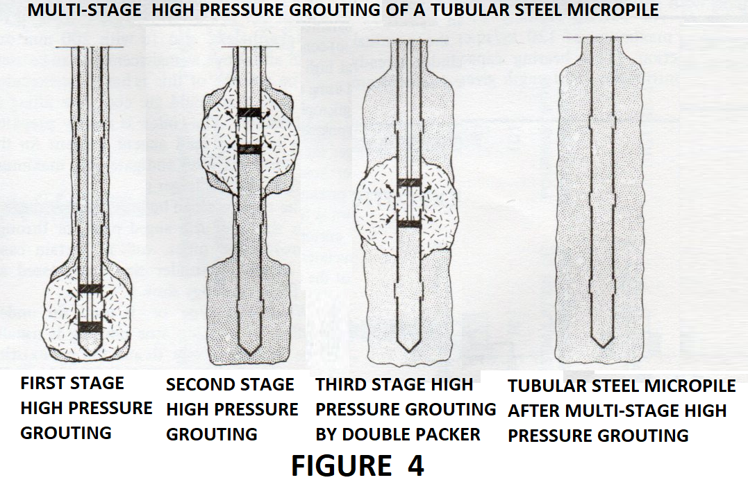
Once the tubular steel micropile reinforcement is installed (with closed bottom, and manchette holes, as already stated above), and with the annular grouting in place as described here above, the annular grouting will be ready to be cracked after 8 to 10 hours from the time of its placing: at that time the grout will be set, but will not be too hard as yet, so, just by applying water under high pressure to each grout hole, by using a double packer, the annular grouting covering the particular grout hole, will crack, and the cracks will remain open, as needed for the cement grout to exit the annular grouting. The cracking, to be done by use of double packer and water under high pressure in correspondence of each manchette hole, is necessary as stated above, to open the way for, and permit the multi-stage performance of high-pressure injections of cement grout thru each manchette.
In cohesive soil formation fix quantity of grout will be injected at a pre-determined high pressure thru each manchette, only once, maintaining the pressure for a while. The residual pressure shall be 1 to 2 Atm.
The soil formation concerned by the micropiles installation in JG Summit Batangas is cohesionless, in fact the soil investigation reports sandy soil, and the procedure to be followed is totally different from what is done in cohesive ground. Tendency of grout injected at high pressure in sand is to produce a phenomenon that is usually referred to with its French term:” claquage” an example of which is shown in Figure 6 here-below.
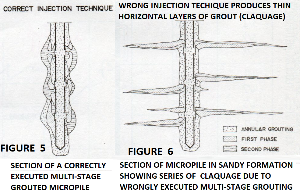
The end result of the procedure to be followed in granular soil, to build up grout bulbs which increase the micropile’s lateral surface (skin) and consequently its bearing capacity by skin friction, is visualized in Figure 5, by the vertical section of an high pressure grouted tubular steel micropile with manchettes.
The pressure grouting of micropiles in granular, non-cohesive soil formations is done by performing a first grouting at low pressure of a predetermined fix quantity of grout, the purpose of using initially low pressure is to keep the grout as close as possible to the tubular reinforcement, and the sequence of pressure grouting will be as in Figure 4. Once all the grout holes have been grouted, the operation will be repeated starting from pile bottom, with the same sequence, grouting a fix quantity of grout at a slightly higher pressure than previously done, this second stage grout will compress against the surrounding soil the previously injected grout (already set). The sequence will be repeated until the volume of grout injected thru each valve will be at least double the volume of the pile section concerned by each grout hole. However, the volume injected is not the only parameter to be observed to gauge the results of the grouting, which should produce a pile configuration as shown in figure 5. The second parameter to be used to determine the efficiency of the pressure grouting performed, is the “residual pressure” which will be fixed by the design.