Jet-Grout Technologies by Foundation Specialists, Inc.
Foundation Specialists Inc. [FS] has developed in 1983 in the Philippines, its own methods and tools for the execution of Jet-Grout, adapted to the prevailing local soil conditions, i.e. high water table, soil formations prone to liquefaction during seismic events, and a relatively high seismicity.
Before Proposing the use of the FS Jet Grout Technologies to Clients, FS had, conducted extensive trials during the whole year1983, in testing areas chosen for the very poor soil conditions, (a) within the Reclamation Area at that time created by the Construction & Development Corporation of the Philippines (CDCP), (b) along the reclaimed portions of CDCP- FS R-10 Road Project in Manila & Navotas, (c) in the (at that time) swamp of Dagat Dagatan in Navotas MM, d) in the area of National Steel Corp0ration Plant along the shores of Iligan Bay. After 1 week curing period, the Jet-Grout Columns or Piles were cored and the core tested in Laboratory for compressive strength, shear strength and cement content. Third Party Consulting Engineers were invited and witnessed the trials
Results of tests conducted on the treated soil were then compared with the results of field and Lab Tests Conducted on the original untreated soil, to evaluate the degree of improvement produced by Jet-Grouting.
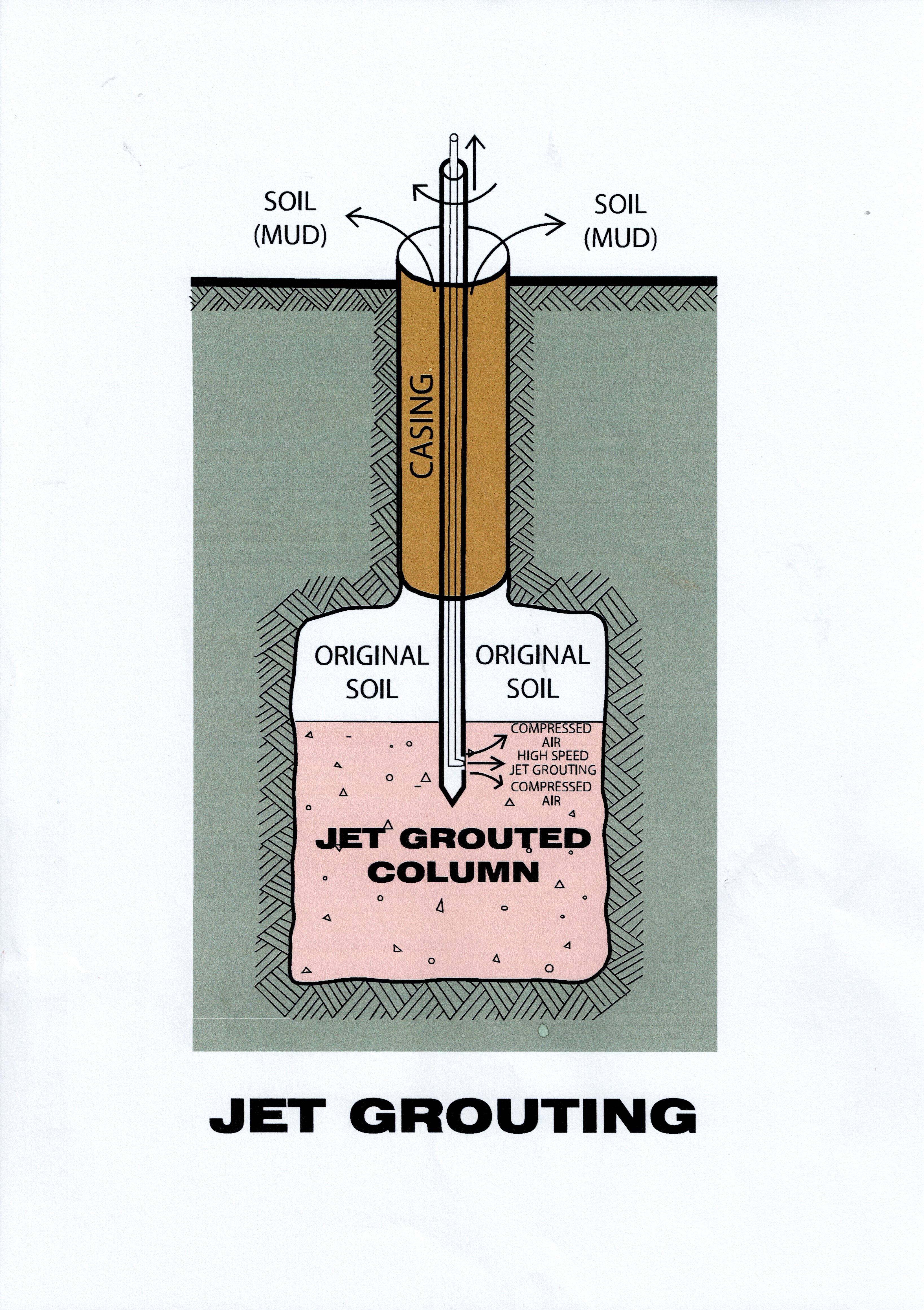
Initially FS had developed three Jet-Grout technologies, 1) Mechanical Deep Mixing “”FS SOIL-CEMENT COLUMNS”” with one fluid component , i.e. Cement Grout to be jetted from within the mixing tool ; 2) Two Components FS Jet-Grout to be directly Jetted by the “Monitor” into the surrounding soil, Water jetted at very high speed , and Cement Grout likewise jetted at high speed from two distinct nozzles of the Monitor; 3) Three Components FS Jet-Grout also to be directly jetted from 3 distinct nozzles of the Monitor, Water, followed by Cement Grout and by compressed air, where the compressed air has the function of extending the reach of the grout into the surrounding ground fractured by the water jetting. The Procedures developed by FS were described by a “paper” of Dr. Armando Cazzola, published on the Philippine Institute of Civil Engineers (PICE) Journal.
Both Jet Grout Methods, 2 and 3 are most indicated for “Alluvium” formations. i.e. formations composed of fines and gravel, pebbles and boulders, where the fines are floated and removed upwards and above ground by the high speed water jets, and replaced by cement grout to eventually form a sort of cyclopean concrete. Jet Grout Method 1 is instead most indicated for clay, silt, sand formations , which are mechanically, intimately, mixed with cement grout .
Methods 2 & 3 float and remove as liquid mud most or all of the fines, and replace it with cement grout, while Method 1 mixes the in situ soil with Cement Grout. In silt and clay the quantity of soil to be removed to disposal is mostly equal to the volume of grout injected, while in sandy soil formations with high percentage of voids the soil to be disposed is near zero in volume, since the cement grout displaces interstitial water and fills the voids so produced.
For FS Soil- Cement Columns the most common diameter is 800MM, but the Method can be very efficiently executed also with smaller and larger diameters. The diameter of the mixing tool used for the FS Soil Cement Columns is exactly the same as the diameter of the columns specified by the designe. The strength of the improved soil is verified by coring the columns and testing the cores in Lab by Unconfined Compression Test.
Proper design pattern of jet grout eliminates the potential for liquefaction of the areas treated, so the FS Soil Cement Columns is the designers’ favorite system for Tanks Foundations in Tank Farms , Warehouses, Bridge Approaches, Slope Protection, Excavation Support, Buildings’ Foundations, Underpinning of Structure, Cofferdams, Pre-consolidation in preparation for Large Diameter Piles or DW in unstable soil formations;, Bottom Plugs to seal bottom of pits, and as FS Composite Soil-Cement Columns (with “I”-beams embedded in it), used as Diaphragm Walls, Fs has successfully completed already hundreds of jet grout projects, in various Countries, with FS Soil Cement Columns having the Lion’s share of it.
INTRODUCING TWO NEW JET_GROUT METHODS:
In 1991, while FS was the General Contractor constructing the 4th ADB “Dapitan Manukan Road Project and the Polo Bridge in Zamboanga Del Norte, part of the work was to stop the sinking and rehabilitate several Box Culverts which were underscoured by heavy floods. To restore proper ground support to the underscoured Box Culvert FS proposed to use Jet Grouting. Soil Cement Jet Grout required the opening of too many large holes on the top and bottom slabs of Box Culvert, to allow the passage of the mixing tool, and we decided to consolidate the soil under the Box Culverts with a “modified” FS Types 2 and 3 Jet Grout. The “modified Method consisted of the original method minus the high-speed water jetting. The scoured sandy soil underneath the Culberts was then subjected to a high-speed Jet Grouting of Cement Grout. The speed of the Grout Jets was increased by employing a pump which produced high speed and large volume of grout suitable to perform at once the fine fragmentation of the soil and the impregnation of the “fragmented” soil by Cement Grout The results were found to be excellent and FS proceeded to consolidate the ground underneath the Box Culvert with that method which was dictated by local conditions. It was thus that the Methods 4 and 5 were created and immediately applied, with success.
Method 4) , Jetting at very high speed One Fluid to break and impregnate the soil formation i.e. jetting at high speed Cement Grout only, to breaks and impregnate the soil.
Method 5), of Jet-Grouting is a variant of the Fourth Method, with the addition of the introduction of Compressed Air, which sharply increases the reach of the Cement Grout and thus creates Jet- Grout Piles of considerably larger diameter than those created by Method No.4.